Recently, CONSOL Energy announced it would be open a new mining operation on the Itmann Mine in West Virginia, and I’ve subsequently been fielding reference requests for information about Itmann and other mines in West Virginia. I haven’t spoken much previously about our mine maps in the Pocahontas Mines Collection, Ms2004-002, and this seems like the perfect time. The collection documents the development of the Pocahontas Coal Seam in southwest Virginia and West Virginia by CONSOL Energy, Inc., and its predecessors in the area. I have been working with the collection since late 2014 and several SCUA staff had been involved with it since the collection first arrived in 2004. The collection is a behemoth with 7,000 maps, about 3,000 survey books and ledgers, numerous photographs, and much more. It totals over 600 cubic feet in almost 800 boxes (but it’s not the largest collection I’ve worked on here!) We also have over 3,600 digital files of mine maps and other documents that I’m still creating metadata for!

When I was processing the collection a few years ago, I was very fortunate to have a student majoring in mining and minerals engineering here at Tech working on the project. Ryan Mair graduated in 2016, but before he left, he drafted a couple of blog posts about the collection, since he had extensive knowledge about it and the mining industry.
One of the blog posts by Ryan Mair, about the Itmann Mines, follows:

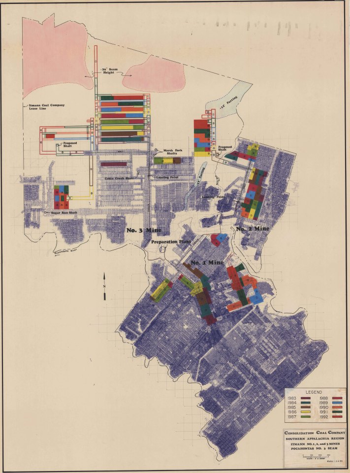
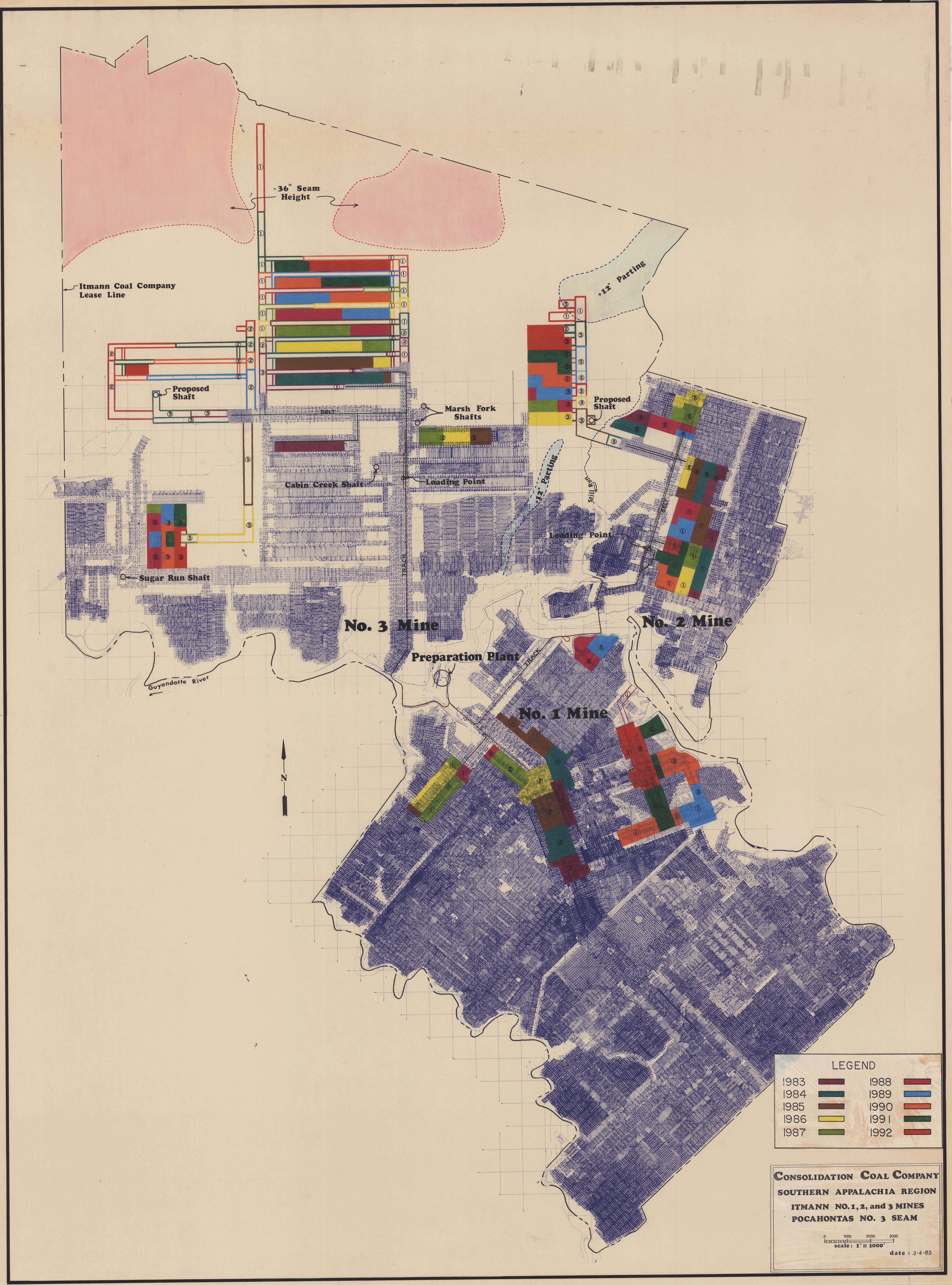
This map in Figure 1 is a production scheduling map of the Itmann No. 1, 2, & 3 Mines as operated by the Consolidation Coal Company. Maps of this type are used to depict the planned progression of mining operations with respect to a standard unit of time. This particular map progresses each future section of mining by year. The production schedule presented by this map was to start in 1983 and continue until the year 1992. The colored sections of the map represent what year coal production will occur in that area of the mine. the darker blue lines of the map depict the outline of the mine workings underground. Black lines are used to depict the property lease line and surface features, such as the buildings of the preparation plan.
These mines extracted coal from the No. 3 seam of the famous Pocahontas Coalfield. Coal from the Pocahontas seams was highly sought after because of its rare quality. This coal contains low amounts of sulfur and hydrocarbons known as “volatile matter” and leaves behind less ash material than most other coals. Pocahontas coal was especially prized by the U.S. Navy because it produces high temperatures while emitting little to no visible smoke when burned. Using this type of “smokeless” coal makes it harder to spot coal burning ships on the open sea. During World War II, the majority of coal from the Pocahontas seams were used to fire coal boilers for the U.S. Navy.

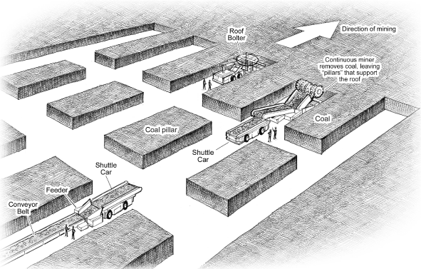
The mines depicted in the Itmann map (Figure 1) use two different methods to extract coal from the earth. Mines No. 1 and No. 2 use a conventional method called room and pillar mining, as seen in Figure 2. Room and pillar mining entails the extraction of coal while leaving large columns or “pillars” behind to support the rock overhead which is called the “back”, “roof”, or “top”. The open area left around the pillar is called the “room”. The shape of the pillars is typically that of a square or rectangle. Pillar dimensions vary with every mine design but are reliant upon the mechanical properties of the coal and the geological stresses present in the mine.
The No. 1 & 2 mines have completed their normal room and pillar mining operations and are recovering coal via a process known as “retreat mining.” Retreat mining is the selective excavation of the pillars to allow a controlled collapse of the mine roof while working towards the mine entrance. Retreat mining is done at the end of the life of a mine when the coal deposit had been depleted through normal room and pillaring. Normal room and pillar coal mines typically recover 40-45% of the coal located within the property. Mining the pillars upon retreat from a room and pillar mine allows operators to increase coal recovery to around 60%. Retreat mining is not always done due to the danger associated with it the unpredictable nature of the roof collapse. By removing selected pillars the mine roof or back is allowed to collapse while additional stress is placed on the remaining pillars. In some cases too much stress can be placed on a pillar. When a pillar reaches its maximum stress and fails, it shatters, sending rock and coal fragments violently through the air followed by the caving of roof around the area where the pillar once stood. This event is known as a pillar “burst” or “bump.” Many miners have died as a result of being near a pillar bump.

The No. 3 Mine in the northwestern part of the Itmann map (Figure 1) employs some room and pillar mining but its main design employs a method know as “longwall mining”. Longwall mining involves the complete extraction of coal from the working area using a “shearer” or “sled” that mines into a large wall or “face” of coal while moving parallel to that wall. A diagram of this method can be seen in Figure 3. As the machine cuts the coal free from the working face, an armored conveyor running parallel with the face transports the coal away. As the cutting and conveyor system move forward, it leaves the unsupported rock layers above to cave in a controlled manner in an area behind the machine. This caved area of roof rock is call the “gob” or “goaf”.
To protect the longwall mining system and the miners at the working face, numerous large hydraulic shields support the roof near the working face. These shields advance with each pass of the cutting head across the face. Longwall mines have considerably faster production capacities than traditional room and pillar mining but have more delays associated with the step and transportation of the equipment.
A working section of a longwall mine is known as a “panel” and are typically 800-1,500 ft. in width and 9,000-15,000 ft. long. Before mining the panel must be developed by what are called the “bleeder” entries. The bleeders serve to open up a path to the area while providing pathways for the ventilation of fresh air to the area. The bleeders are especially needed in the case of mining coal that contains high amounts of entrapped methane gas which is highly combustible. With the bleeder it is possible to degas or render the gas inert with enough fresh airflow. The pillars in bleeder entries are often called chain pillars and are left intact throughout the life of the mine to protect the ventilation and passageways.
In the northern section of the Itmann map (Figure 1), there are two geologic features that are identified. The two areas shaded in red denote areas where the coal on the property is less than 36 inches thick. Areas of deep underground coal that are less than 36 inches of coal are essentially too thick to mine profitably. Additionally, such areas make it difficult for both miner and machine to maneuver effectively. The second feature, shaded in light blue, is an area of coal with what is called a “parting,” a layer of non-coal rock that formed within the coalbed and parts the coal seam. Partings can be less than one inch to several feet in thickness. Thick partings are areas of coal to avoid when mining since the harder rock of the parting can excessively wear or damage cutting heads and requires more intense processing of the coal material at the surface plant.

The Itmann No. 3 mine shown in this map (Figure 1) was the scene of a mine disaster in December 1972. On December 16th, 1972, eight day shift miners had finished their shift and were exiting their working area of the Cabin Creek 4-Panel via an electrically powered rail car known as a portal bus (Figure 4). Unbeknownst to the miners, highly explosive methane gas had built up in the section. While in motion the portal bus trolley wire harp, which transfers electricity from the trolley wire to the portal bus, briefly disconnected from the wire. Such disconnections are common and are part of the design of the system but often result in an electrical sparking. Within the first 1,000 ft of the miners’ journey out of the mine just such an electrical spark occurred. This electrical sparking caused the ignition of the surrounding methane gas and propagated into an explosive wave. The blast wave and flames killed five miners instantly and seriously burned the other three. The blast force was also strong enough to blow out 14 permanent stoppings of cinderblock construction in the section.
Resources:
- Pocahontas Mines Collection, Ms2004-002, Virginia Tech Special Collections and University Archives, https://ead.lib.virginia.edu/vivaxtf/view?docId=vt/viblbv01918.xml
- “CONSOL Energy Announces Development of the Itmann Mine,” CONSOL Energy, May 8, 2019. http://investors.consolenergy.com/2019-05-08-CONSOL-Energy-Announces-Development-of-the-Itmann-Mine
- “Historical Summary of Coal Mine Explosions in the United States, 1959-81,” By J. K. Richmond, G. C. Price, M. J. Sapko, and E. M. Kawenski, Information circular 8909, United States Department of the Interior, Bureau of Mines. https://www.cdc.gov/niosh/ mining/userfiles/works/pdfs/ic8909.pdf
- “Form 10-K, Annual Report Pursuant to Section 13 or 15(d) of the Securities Exchange Act of 1934 for the fiscal year ended December 31, 2009,” Commission file number: 1-13105, ARCH COAL, INC., https://www.sec.gov/Archives/edgar/data/1037676/000095012310019343/ c55409e10vk.htm
- “Itmann Coal Company, Itmann No. 3 Mine Explosion,” United States Mine Rescue Association, https://usminedisasters.miningquiz.com/saxsewell/itmann.htm
- “Official Report of Major Mine Explosion Disaster, Itmann No. 3 Mine (ID 46-01576), Itmann Coal Company, Itmann, Wyoming County, West Virginia, December 16, 1972” by W. R. Park, Sylvester E. Gaspersich, and Fred E. Ferguson, of the Office of Coal Mine Health and Safety, U.S. Department of the Interior, Bureau of Mines, from the United States Mine Rescue Association, https://usminedisasters.miningquiz.com/saxsewell/itmann_1972.pdf
- “Itmann, WV Coal Mine Explosion, Dec 1972” with transcript of “Explosion at Itmann Kills 5 Miners. Three Rescued in ‘Critical’ Condition.” from the Post Herald and Register, Beckley, West Virginia, 1972/12/17, GenDisasters.com, http://www.gendisasters.com/west-virginia/19804/itmann-wv-coal-mine-explosion-dec-1972

Excellent work. My father worked at the tipple running the rotary dump.
He spoke often a drainage way that drained the water from Itman thru to the Bishop mine.
Are there maps of this drainage way on record?
Thank you for your work. I’m happy to see as well there is still coal that Itman will get one last dance. My dad is smiling from heaven!!